thank you for visiting this website !!!!!!!!!!
Anatomy of a Two-Point Source Interference Pattern
Lesson 1 of this unit of The Physics Classroom Tutorial focused on the nature of light as a wave. Evidence that led scientists to believe that light had a wavelike nature was presented. One piece of evidence centered around the ability of one light wave to interfere with another light wave. This interference is most obvious if monochromatic light from two coherent sources is allowed to interfere. In Lesson 3 of this unit, we will focus upon the mathematical nature of two-point source light interference. The relationship between the wavelength of light and the specific features of a two-point source interference pattern will be described. The means by which Thomas Young used this relationship to measure the wavelength of light will be discussed.In Lesson 1, the nature of the interference pattern produced by two bobbing sources in a ripple tank (water tank) was discussed.
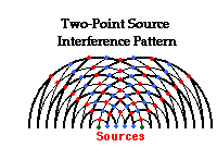 The
diagram at the right depicts the pattern resulting from the propagation
of water waves across the surface of the water. The waves propagate
outward from the point sources, forming a series of concentric circles
about the source. In the diagram, the thick lines represent wave crests
and the thin lines represent wave troughs. The crests and troughs from
the two sources interfere with each other at a regular rate to produce
nodes (pictured in blue on the diagram) and antinodes (pictured in red)
along the water surface. The nodal positions are locations where the
water is undisturbed; the antinodal positions are locations where the
water is undergoing maximum disturbances above and below the surrounding
water level. One unique feature of the two-point source interference
pattern is that the antinodal and nodal positions all lie along distinct
lines. Each line can be described as a relatively straight hyperbola.
The spatial separation between the antinodal and nodal lines in the
pattern is related to the wavelength of the waves. The mathematical
relationship will be explored later in this lesson. For now, we will
investigate the underlying causes of this unique pattern and introduce
some nomenclature (naming conventions) that will be utilized throughout
the lesson.
The
diagram at the right depicts the pattern resulting from the propagation
of water waves across the surface of the water. The waves propagate
outward from the point sources, forming a series of concentric circles
about the source. In the diagram, the thick lines represent wave crests
and the thin lines represent wave troughs. The crests and troughs from
the two sources interfere with each other at a regular rate to produce
nodes (pictured in blue on the diagram) and antinodes (pictured in red)
along the water surface. The nodal positions are locations where the
water is undisturbed; the antinodal positions are locations where the
water is undergoing maximum disturbances above and below the surrounding
water level. One unique feature of the two-point source interference
pattern is that the antinodal and nodal positions all lie along distinct
lines. Each line can be described as a relatively straight hyperbola.
The spatial separation between the antinodal and nodal lines in the
pattern is related to the wavelength of the waves. The mathematical
relationship will be explored later in this lesson. For now, we will
investigate the underlying causes of this unique pattern and introduce
some nomenclature (naming conventions) that will be utilized throughout
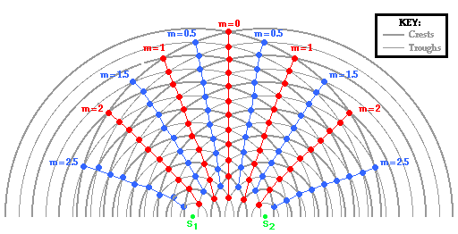
the lesson.The animation below shows a series of concentric circles about two point sources (labeled as S1 and S2). The pattern could be the result of water waves in a ripple tank resulting from two vibrating sources; or the result of sound waves from two speakers traveling through a room; or the result of two light waves moving through a room after passing through two slits or pinholes in a sheet of paper. Like the diagram above, the thick lines represent wave crests and the thin lines represent wave troughs. The red dots in the animation represent the antinodal positions; the blue dots represent the nodal positions. The red lines drawn through the antinodal points (red dots) are referred to as antinodal lines and the blue lines drawn through the nodal points (blue dots) are referred to as nodal lines.
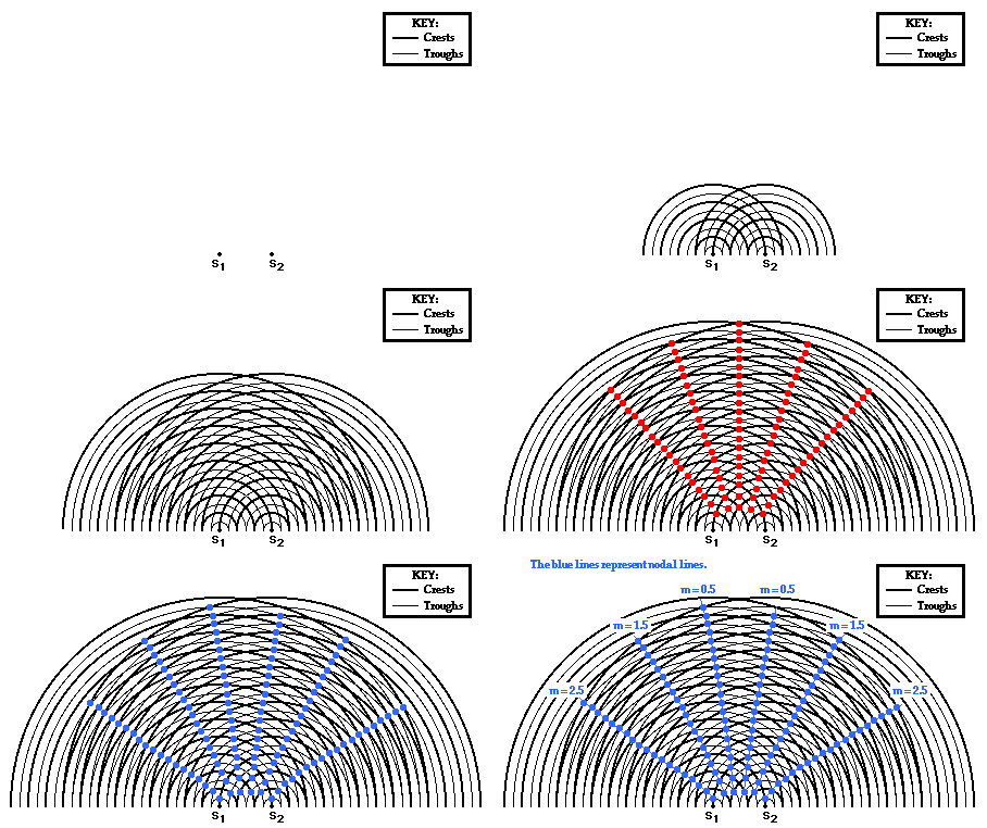
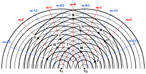
Each line in the pattern is assigned a number, known as the order number and represented by the letter m. The numbering system associated with this pattern is just as creative as the naming system. The central antinodal line is assigned an order number of 0. The first antinodal line is assigned an order number of 1; the second antinodal line is assigned an order number of 2; the third antinodal line is assigned an order number of 3; etc. Nodal lines are assigned half-numbers. The first nodal line, located between the central antinodal line (m = 0) and the first antinodal line (m = 1) is assigned the order number of 0.5. The second nodal line, located between the first antinodal line (m = 1) and the second antinodal line (m = 2) is assigned the order number of 1.5. Finally, the third nodal line, located between the second antinodal line (m = 2) and the third antinodal line (m = 3) is assigned the order number of 2.5. Subsequently, if one were to start in the center of the pattern and observe the lines (both antinodal and nodal) and associated numbers to the left or to the right of the central antinodal line, the numbers would start at 0 and increase by one-half:
Check Your Understanding
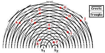
a. ... on nodal lines? b. ... on antinodal lines?
c. ... formed as the result of constructive interference?
d. ... formed as the result of destructive interference?
2. Observe the two-point source interference pattern shown below. Several points are marked and labeled with a letter.
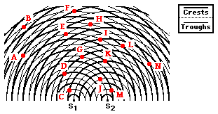
a. ... on the central antinodal line? b. ... on the first antinodal line?
c. ... on the second antinodal line?
d. ... on the first nodal line?
e. ... on the second nodal line?
f. ... on the third nodal line?
ANSWERS:
1.a. Nodal Lines: A, B, D, G (Look for the interference of crests with troughs; that is, thick and thin lines.)
b. Antinodal Lines: C, E, F, H, I, J (Look for the interference of crests with crests or troughs with troughs; that is, thick and thick lines or thin and thin lines.)
2. a. Central Antinodal Line (m = 0): H
b. First Antinodal Line (m = 1): E, J, K
c. Second Antinodal Line (m = 2): B, D
d. First Nodal Line (m = 0.5): F, G, I
e. Second Nodal Line (m = 1.5): L
f. Third Nodal Line (m = 2.5): A, C, M, N
The Path Difference
To begin, consider the pattern shown in the animation below. Point A is a point located on the first antinodal line. This specific antinode is formed as the result of the interference of a crest from Source 1 (S1) meeting up with a crest from Source 2 (S2). The two wave crests are taking two different paths to the same location to constructively interfere to form the antinodal point.
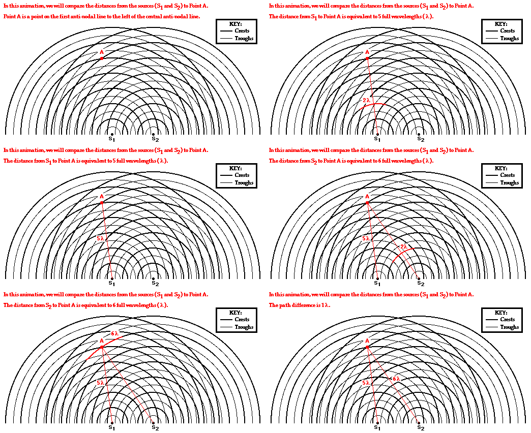
For point A on the first antinodal line (m =1), the path difference is equivalent to 1 wavelength. But will all points on the first antinodal line have a path difference equivalent to 1 wavelength? And if all points on the first antinodal line have a path difference of 1 wavelength, then will all points on the second antinodal line have a path difference of 2 wavelengths? And what about the third antinodal line? And what about the nodal lines? These questions are investigated in the diagrams below through the analysis of the path difference for other points located on antinodal and nodal lines.
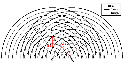
Point B in the diagram below is also located on the first antinodal line. The point is formed as a wave crest travels a distance of 3 wavelengths from point S1 and meets with a second wave crest that travels a distance 4 wavelengths from S2. The difference in distance traveled by the two waves from their sources to point B is
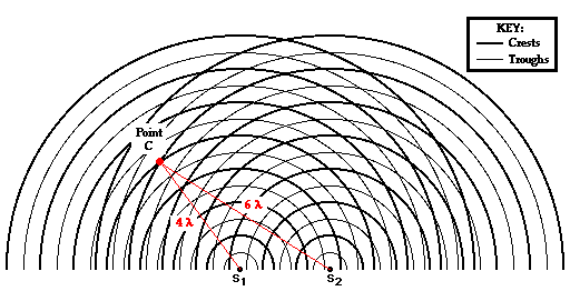
Now we will analyze Point C, which is located on the second antinodal line (see the diagram below). The point is formed as a wave crest travels a distance of 4 wavelengths from point S1 and meets with a second wave crest that travels a distance 6 wavelengths from S2. The difference in distance traveled by the two waves from their sources to point C is
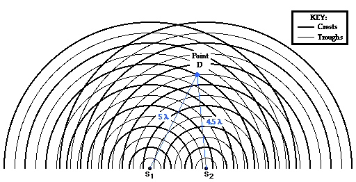
The analysis continues for this same pattern as we explore the path difference for locations on nodal lines. Point D is located on the first nodal line (see the diagram below). The point is formed as a wave crest travels a distance of 5 wavelengths from point S1 and meets with a wave trough that travels a distance 4.5 wavelengths from S2. The difference in distance traveled by the two waves from their sources to point D is
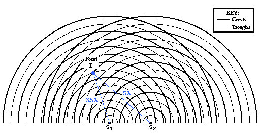
Point E in the diagram below is located on the second nodal line. The point is formed as a wave trough travels a distance of 3.5 wavelengths from point S1 and meets with a wave crest that travels a distance 5 wavelengths from S2. The difference in distance traveled by the two waves from their sources to point E is
The information in the above analyses is summarized in the table below. Other points on other antinodal and nodal lines are marked on the diagram below and their distance from the sources and their path difference are also summarized in the same table. Inspect the table and see if you can find a pattern evident in the numbers.
or Node? |
(m) |
from S1 (in λ) |
from S2 (in λ) |
Difference (in λ) |
|
Antinodal Points:
|
||
Nodal Points:
|
Explaining the Path Difference Equation
A tedious inspection of a variety of antinodal and nodal points on a typical pattern reveals the above relationships. But why? Why would constructive interference occur when the difference in distance traveled by two waves is equivalent to a whole number of wavelengths? And why would destructive interference occur when the difference in distance traveled by two waves is equivalent to a half number of wavelengths? To answer these questions, consider the diagrams below.The diagram below shows two waves traveling along different paths from different sources to the same point in such a way that a crest is meeting a crest. Constructive interference will occur at this point. The wave from Source 1 (S1) travels a distance of 6 wavelengths (you can trace your finger over the wave to help you count wavelengths). The wave from Source 2 (S2) travels a distance of 7 wavelengths to reach the same point. The difference in distance traveled by the two waves is one full wavelength. That is, the path difference is 1 λ. When the path difference is one full wavelength, a crest meets a crest and constructive interference occurs.

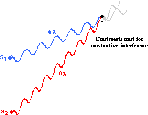
How does a path difference of two wavelengths cause constructive interference? The diagram below shows this. Two waves traveling along different paths from different sources meet at the same point in such a way that a crest is meeting a crest; constructive interference occurs. The wave from Source 1 (S1) travels a distance of 6 wavelengths. The wave from Source 2 (S2) travels a distance of 8 wavelengths to reach the same point. The difference in distance traveled by the two waves is two full wavelengths; that is, the path difference is 2 λ. When the path difference is two full wavelengths, a crest meets a crest and constructive interference occurs.
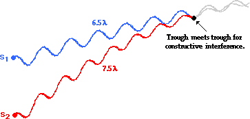
The previous two examples involve the meeting of a crest with a crest. Under what conditions will a trough meet a trough? The diagram below depicts this. Once more, the two waves travel different paths from their different sources and meet in such a manner to constructively interfere; only this time the constructive interference results from a trough meeting a trough. Observe that the wave from Source 1 (S1) travels a distance of 6.5 wavelengths. The wave from Source 2 (S2) travels a distance of 7.5 wavelengths to reach the same point. The difference in distance traveled by the two waves is one full wavelength; that is, the path difference is 1 λ.
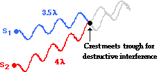
The above examples pertain to the constructive interference that occurs for locations on antinodal lines. In each case, a path difference of a whole number of wavelengths causes a crest to meet a crest or a trough to meet a trough. But what about destructive interference? The diagram below depicts the destructive interference of two waves from the sources. Observe that the wave from Source 1 (S1) travels a distance of 3.5 wavelengths. The wave from Source 2 (S2) travels a distance of 4 wavelengths to reach the same point. The difference in distance traveled by the two waves is one-half a wavelength; that is, the path difference is 0.5 λ. Whenever the two waves have a path difference of one-half a wavelength, a crest from one source will meet a trough from the other source. Destructive interference occurs for path differences of one-half a wavelength.
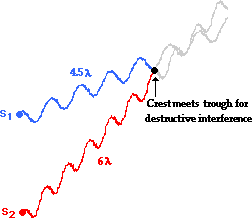
An additional example of destructive interference is shown below. Observe that the wave from Source 1 (S1) travels a distance of 4.5 wavelengths. The wave from Source 2 (S2) travels a distance of 6 wavelengths to reach the same point. The difference in distance traveled by the two waves is three-halves a wavelength; that is, the path difference is 1.5
In summary, the analysis of the two-point source interference patterns reveals the following equations:
Antinodal Points:
|
||
Nodal Points:
|
In the next part of Lesson 3 we will investigate the nature of a two-point source light interference and make the connection between these simple ripple tank patterns and the observations made by Thomas Young when he first demonstrated two-point source light interference in the early 1800s.
Check Your Understanding
2. Two point sources are generating periodic waves in phase. The wavelength is 4.0 cm. A point on the second antinodal line is 30.0 cm from the nearest source. How far is this point from the farthest source? Begin by constructing a sketch of the physical situation. PSYW
3. Two point sources are generating periodic waves in phase. The wavelength of the waves is 3.0 cm. A point on a nodal line is 25 cm from one source and 20.5 cm from the other source. Construct a sketch of the physical situation and determine the nodal line number. PSYW
4. Two point sources are generating periodic waves in phase. A point on the fourth nodal line is 25.0 cm from one source and 39.0 cm from the farthest source. Construct a sketch of the physical situation and determine the wavelength. PSYW
1.Answer: 0.667 cm The distances from the sources to the antinode are known: S1P = 8 cm and S2P = 10 cm. And since the antinode lies on the third antinodal line, m = 3. The distances between the sources is known , but will be of little importance. Using PD = m • λ, we can solve for wavelength.
PD = | S1P - S2P | = | 8 cm - 10 cm | = 2 cm.So by substitution,
λ = PD / m = (2 cm) / 3 = 0.667 cm
2.Answer: 38 cm
"Point P" is on the second antinodal line, so m = 2. The wavelength (λ) is 4.0 cm. From the equation PD = m • λ, the path difference (PD) can be found.
PD = 2 • 4.0 cm = 8.0 cmSo point P is 8 cm further from the farther source than it is from the nearer source. So if P is 30.0 cm from the nearest souce, then it is 38 cm from the furthest source.
Young's Equation
Antinodal Points:
|
||
Nodal Points:
|
A Light Interference Pattern
As in any two-point source interference pattern, light waves from two coherent, monochromatic sources (more on coherent and monochromatic later) will interfere constructively and destructively to produce a pattern of antinodes and nodes. Light traveling through the air is typically not seen since there is nothing of substantial size in the air to reflect the light to our eyes. Thus, the pattern formed by light interference cannot be seen unless it is somehow projected onto some form of a screen or a sheet of paper. When light from the two sources is projected onto a screen, the pattern becomes quite evident. Locations where light constructively interferes corresponds to an abnormally bright spot. Locations where light destructively interferes corresponds to an abnormally dark spot. That is, the antinodes are locations where light from the two individual sources are reinforcing each other and correspond to points of brightness or maximum intensity (sometimes referred to as maxima). And the nodes are locations where light from the two individual sources are destroying each other and correspond to points of darkness or minimum intensity (sometimes referred to as minima).Red laser light passing through two narrowly spaced slits is typically used in the classroom to produce this effect. Thus, a pattern of bright red and dark fringes or bands is observed on a screen as shown in the diagram below.
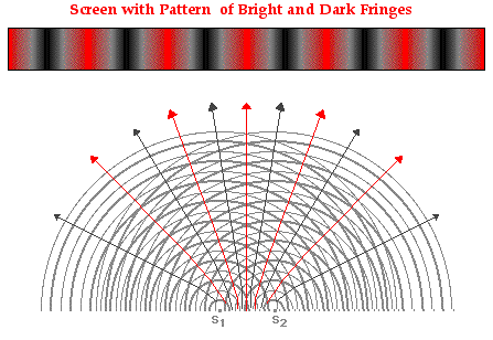
As mentioned earlier in Lesson 3, each antinodal and nodal line is assigned a number or order value (m). The red band of maximum brightness located in the center of screen (the central maximum) is assigned an order number of m = 0. The other bright red bands to the left and the right of the central maximum are assigned whole number values of 1, 2, 3, ... as shown in the diagram below. The dark bands on the pattern are assigned half number values of 0.5, 1.5, 2.5, ... as shown in the diagram below.

Derivation of Young's Equation
In 1801, this experiment was performed for the first time by Thomas Young. Young expanded the mathematical model presented above by relating the wavelength of light to observable and measurable distances. Today, an experimental setup similar to that of Thomas Young's is commonly used in a Physics classroom to repeat the experiment and to measure the wavelength of light. In the experiment as it is commonly performed today, light from a laser beam is passed through two narrowly spaced slits in a slide or sheet of paper. The light diffracts through the slits and interferes in the space beyond the slits. Thus, the slits serve as the two sources. The interference pattern is then projected onto a screen, paper or a whiteboard located several meters away. The spatial separation of nodes and antinodes on the screen is clearly seen.
The diagram below on the left depicts two sources labeled S1 and S2 and separated by some distance d. Point P is a point on the screen that happens to be located on some nodal or antinodal line; as such, there is an order value (m) associated with this point. Point C is the central point on the screen. The distance from point P to point C as measured perpendicular to the central antinodal line will be referred to as y. The screen is located a distance of L from the sources. In the following derivation, the wavelength of light will be related to the quantities d, m, y and L.
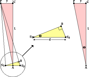
The yellow triangle in the diagram on the left above is enlarged and redrawn in the middle of the graphic. The triangle is a right triangle with an angle theta and a hypotenuse of d. Using the sine function, it can be stated that
The second set of corresponding angles of equal measure is
If the pink triangle (∆S1BS2) and the yellow triangle (∆ACP) are similar, all corresponding angles are equal in measure, and so
As set forth by the derivation above, the wavelength of laser light can be experimentally determined by selecting a point (referred to as point P) on a nodal and antinodal line of known order value (m) and making the following measurements:
- the distance between the slits or sources of the two light waves (d)
- the perpendicular distance from the point P to a point on the central antinodal line (y)
- the distance from point P to the sources (L)
The Importance of Coherent Light Sources
Visible light waves - those that humans can see - have an abnormally short wavelength. For instance, red light has a wavelength of about 650 nanometers. Since there are one billion nanometers in a meter, and one thousand millimeters in a meter, the wavelength of red light is less than one-thousandth of a millimeter. That's a very short wave. And being a short wave, the distance between positions of constructive interference and positions of destructive interference is very small. Thus, the effects of interference for visible light waves are difficult to observe.Complicating the task of observing the interference of visible light waves is the fact that light from the two sources must be coherent. Two light sources that maintain a constant phase difference with each other are said to be coherent light sources. Light visible to the human eye makes a complete cycle of vibration from crest to trough and back to crest in roughly 10-15 seconds. If we think of a light wave as a transverse wave pattern with crests and troughs, then a crest is typically created every 10-15 seconds. Consider two light sources producing light waves at the same frequency, but one source is creating a crest just prior to the moment in time when the other source is creating a crest. Such light sources are not at the same phase in their cycle of light production. They are said to be out of phase. Yet if they maintain the same difference in phase, they are considered coherent light sources. Even if the sources of light do not stay in step with each other, as long as the amount by which they are out of step remains the same over time, the light sources are said to be coherent.

In this section, the logic and mathematics associated with Young's equation was presented. In the next section of Lesson 3, we will investigate how Thomas Young was able to conduct an experiment with two coherent sources of light in order to make a reliable measurement of the wavelength of light.
Check Your Understanding
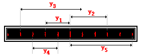 1.
When determining the wavelength of light, measurements must be made of
y, d, m and L. The y value is dependent upon the chosen dark or bright
spot and thus the m value. Consider the projected pattern of bright and
dark spots on a screen as shown below. For each y measurement, identify the corresponding m
value. Then see if you can observe a generality about the relationship
between the spacing between adjacent bright spots and the y and m value.
1.
When determining the wavelength of light, measurements must be made of
y, d, m and L. The y value is dependent upon the chosen dark or bright
spot and thus the m value. Consider the projected pattern of bright and
dark spots on a screen as shown below. For each y measurement, identify the corresponding m
value. Then see if you can observe a generality about the relationship
between the spacing between adjacent bright spots and the y and m value.2. Young's equation describes the mathematical relationship between wavelength and measurable quantities in a two-point source interference experiment.
a. Altering the distance between sources (d) by a factor of 2 would cause the y value to ____________ (increase or decrease) by a factor of _____. b. Altering the distance between sources (d) by a factor of 0.5 (one-half) would cause the y value to ____________ (increase or decrease) by a factor of _____.
c. Altering the distance between the sources and the screen (L) by a factor of 3 would cause the y value to ____________ (increase or decrease) by a factor of _____.
d. Altering the distance between the sources and the screen (L) by a factor of 0.25 (one-fourth) would cause the y value to ____________ (increase or decrease) by a factor of _____.
e. Altering the wavelength of light (λ) by a factor of 1.5 (three-halves) would cause the y value to ____________ (increase or decrease) by a factor of _____
ANSWERS:
1.This question targets the effect of alterations in d, L and λ upon the spacing between bright spots (y). Thus, the first place to begin involves re-arranging Young's equation so that y is by itself on one side of the equation:
a. Altering the distance between sources (d) by a factor of 2 would cause the y value to decrease by a factor of 2. That is, the y value will be one-half its original value.
b. Altering the distance between sources (d) by a factor of 0.5 (one-half) would cause the y value to increase by a factor of 2. That is, the y value will be two times its original value.
c. Altering the distance between the sources and the screen (L) by a factor of 3 would cause the y value to increase by a factor of 3. That is, the y value will be three times its original value.
d. Altering the distance between the sources and the screen (L) by a factor of 0.25 (one-fourth) would cause the y value to decrease by a factor of 4. That is, the y value will be one-fourth its original value.
e. Altering the wavelength of light (λ) by a factor of 1.5 (three-halves) would cause the y value to increase by a factor of 1.5. That is, the y value will be three-halves its original value.
This question targets the effect of alterations in d, L and λ upon the
spacing between bright spots (y). Thus, the first place to begin
involves re-arranging Young's equation so that y is by itself on one
side of the equation:
y = m • L • λ / d
Now observe that y is directly proportional to the L and λ values and inversely proportional to the d value.
a. Altering the distance between sources (d) by a factor of 2 would cause the y value to decrease by a factor of 2. That is, the y value will be one-half its original value.
b. Altering the distance between sources (d) by a factor of 0.5 (one-half) would cause the y value to increase by a factor of 2. That is, the y value will be two times its original value.
c. Altering the distance between the sources and the screen (L) by a factor of 3 would cause the y value to increase by a factor of 3. That is, the y value will be three times its original value.
d. Altering the distance between the sources and the screen (L) by a factor of 0.25 (one-fourth) would cause the y value to decrease by a factor of 4. That is, the y value will be one-fourth its original value.
e. Altering the wavelength of light (λ) by a factor of 1.5 (three-halves) would cause the y value to increase by a factor of 1.5. That is, the y value will be three-halves its original value.
2.This question targets the effect of alterations in d, L and λ upon the spacing between bright spots (y). Thus, the first place to begin involves re-arranging Young's equation so that y is by itself on one side of the equation:
y = m • L • λ / d
Now observe that y is directly proportional to the L and λ values and inversely proportional to the d value.
a. Altering the distance between sources (d) by a factor of 2 would cause the y value to decrease by a factor of 2. That is, the y value will be one-half its original value.
b. Altering the distance between sources (d) by a factor of 0.5 (one-half) would cause the y value to increase by a factor of 2. That is, the y value will be two times its original value.
c. Altering the distance between the sources and the screen (L) by a factor of 3 would cause the y value to increase by a factor of 3. That is, the y value will be three times its original value.
d. Altering the distance between the sources and the screen (L) by a factor of 0.25 (one-fourth) would cause the y value to decrease by a factor of 4. That is, the y value will be one-fourth its original value.
e. Altering the wavelength of light (λ) by a factor of 1.5 (three-halves) would cause the y value to increase by a factor of 1.5. That is, the y value will be three-halves its original value.
The previous section of Lesson 3 discussed Thomas
Young's effort to derive an equation relating the wavelength of a light
source to reliably measured distances associated with a two-point source
light interference pattern. The equation, known as Young's equation is:
λ = y • d / (m • L)
In 1801, Young devised and performed an experiment to measure the wavelength of light. As discussed in the previous 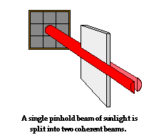 part
of this lesson, it was important that the two sources of light that
form the pattern be coherent. The difficulty confronting Young was that
the usual light sources of the day (candles, lanterns, etc.) could not
serve as coherent light sources. Young's method involved using sunlight
that entered the room through a pinhole in a window shutter. A mirror
was used to direct the pinhole beam horizontally across the room. To
obtain two sources of light, Young used a small paper card to break the
single pinhole beam into two beams, with part of the beam passing by the
left side of the card and part of the beam passing by the right side of
the card. Since these two beams emerged from the same source - the sun -
they could be considered coming from two coherent sources. Light waves
from these two sources (the left side and the right side of the card)
would interfere. The interference pattern was then projected onto a
screen where measurements could be made to determine the wavelength of
light.
Today's classroom version of the same experiment is typically performed using a laser beam as the source. Rather than using a note card to split the single beam into two coherent beams, a carbon-coated glass slide with two closely spaced etched slits is used. The slide with its slits is most commonly purchased from a manufacturer who provides a measured value for the slit separation distance - the d value in Young's equation. Light from the laser beam diffracts through the slits and emerges as two separate coherent waves. The interference pattern is then projected onto a screen where reliable measurements can be made of L and y for a given bright spot with order value m. Knowing these four values allows a student to determine the value of the wavelength of the original light source.

To illustrate some typical results from this experiment and the subsequent analysis, consider the sample data provided below for d, y, L and m.
(Note: AN0 = central antinode and AN4 = fourth antinode)
The determination of the wavelength demands that the above values for d, y, L and m be substituted into Young's equation.
λ = y • d / (m • L)
Careful inspection of the units of measurement is
always advisable. The sample data here reveal that each measured
quantity is recorded with a different unit. Before substituting these
measured values into the above equation, it is important to give some
thought to the treatment of units. One means of resolving the issue of
nonuniform units is to simply pick a unit of length and to convert all
quantities to that unit. If doing so, one might want to pick a unit that
one of the data values already has so that there is one less
conversion. A wise choice is to choose the meter as the unit to which
all other measured values are converted. Since there are 1000
millimeters in 1 meter, the 0.250 mm is equivalent to 0.000250 meter.
And since there are 100 centimeters in 1 meter, the 10.2 cm is
equivalent to 0.102 m. Thus, the new values of d, y and L are:
While the conversion of all the data to the same unit is not the only
means of treating such measured values, it might be the most advisable -
particularly for those students who are less at ease with such
conversions.
Now that the issue regarding the units of measurement has been resolved, substitution of the measured values into Young's equation can be performed.
λ = (0.102 m) • (0.000250 m) / [ (4) • (9.78 m) ]
λ = 6.52 x 10⁻⁷ m
As is evident here, the wavelength of visible light is rather small. For
this reason wavelength is often expressed using the unit nanometer,
where 1 meter is equivalent to 109 nanometers. Multiplying by 109 will convert the wavelength from meters to nanometers (abbreviated nm).
λ = 652 nm
1. The diagram below depicts the results of Young's Experiment. The appropriate measurements are listed on the diagram. Use these measurements to determine the wavelength of light in nanometers. (GIVEN: 1 meter = 109 nanometers)

2. A student uses a laser and a double-slit apparatus to project a two-point source light interference pattern onto a whiteboard located 5.87 meters away. The distance measured between the central bright band and the fourth bright band is 8.21 cm. The slits are separated by a distance of 0.150 mm. What would be the measured wavelength of light?
3. The analysis of any two-point source interference pattern and a successful determination of wavelength demands an ability to sort through the measured information and equating the values with the symbols in Young's equation. Apply your understanding by interpreting the following statements and identifying the values of y, d, m and L. Finally, perform some conversions of the given information such that all information share the same unit.
a. Two slits separated by 0.250 mm produces an interference pattern in which the fifth dark band is located 12.8 cm from the central antinode when the screen is placed a distance of 8.2 meters away.
a. Altering the distance between sources (d) by a factor of 2 would cause the y value to decrease by a factor of 2. That is, the y value will be one-half its original value.
b. Altering the distance between sources (d) by a factor of 0.5 (one-half) would cause the y value to increase by a factor of 2. That is, the y value will be two times its original value.
c. Altering the distance between the sources and the screen (L) by a factor of 3 would cause the y value to increase by a factor of 3. That is, the y value will be three times its original value.
d. Altering the distance between the sources and the screen (L) by a factor of 0.25 (one-fourth) would cause the y value to decrease by a factor of 4. That is, the y value will be one-fourth its original value.
e. Altering the wavelength of light (λ) by a factor of 1.5 (three-halves) would cause the y value to increase by a factor of 1.5. That is, the y value will be three-halves its original value.
2.This question targets the effect of alterations in d, L and λ upon the spacing between bright spots (y). Thus, the first place to begin involves re-arranging Young's equation so that y is by itself on one side of the equation:
a. Altering the distance between sources (d) by a factor of 2 would cause the y value to decrease by a factor of 2. That is, the y value will be one-half its original value.
b. Altering the distance between sources (d) by a factor of 0.5 (one-half) would cause the y value to increase by a factor of 2. That is, the y value will be two times its original value.
c. Altering the distance between the sources and the screen (L) by a factor of 3 would cause the y value to increase by a factor of 3. That is, the y value will be three times its original value.
d. Altering the distance between the sources and the screen (L) by a factor of 0.25 (one-fourth) would cause the y value to decrease by a factor of 4. That is, the y value will be one-fourth its original value.
e. Altering the wavelength of light (λ) by a factor of 1.5 (three-halves) would cause the y value to increase by a factor of 1.5. That is, the y value will be three-halves its original value.
Young's Experiment
 part
of this lesson, it was important that the two sources of light that
form the pattern be coherent. The difficulty confronting Young was that
the usual light sources of the day (candles, lanterns, etc.) could not
serve as coherent light sources. Young's method involved using sunlight
that entered the room through a pinhole in a window shutter. A mirror
was used to direct the pinhole beam horizontally across the room. To
obtain two sources of light, Young used a small paper card to break the
single pinhole beam into two beams, with part of the beam passing by the
left side of the card and part of the beam passing by the right side of
the card. Since these two beams emerged from the same source - the sun -
they could be considered coming from two coherent sources. Light waves
from these two sources (the left side and the right side of the card)
would interfere. The interference pattern was then projected onto a
screen where measurements could be made to determine the wavelength of
light.
 Today's classroom version of the same experiment is typically performed using a laser beam as the source. Rather than using a note card to split the single beam into two coherent beams, a carbon-coated glass slide with two closely spaced etched slits is used. The slide with its slits is most commonly purchased from a manufacturer who provides a measured value for the slit separation distance - the d value in Young's equation. Light from the laser beam diffracts through the slits and emerges as two separate coherent waves. The interference pattern is then projected onto a screen where reliable measurements can be made of L and y for a given bright spot with order value m. Knowing these four values allows a student to determine the value of the wavelength of the original light source.

To illustrate some typical results from this experiment and the subsequent analysis, consider the sample data provided below for d, y, L and m.
Slit Separation (d)
|
|
Distance from Slits to Screen (L)
|
|
Distance from AN0 to AN4 (y)
|
|
Order value (m)
|
|
Now that the issue regarding the units of measurement has been resolved, substitution of the measured values into Young's equation can be performed.
λ = 6.52 x 10⁻⁷ m
Check Your Understanding
1. The diagram below depicts the results of Young's Experiment. The appropriate measurements are listed on the diagram. Use these measurements to determine the wavelength of light in nanometers. (GIVEN: 1 meter = 109 nanometers)

2. A student uses a laser and a double-slit apparatus to project a two-point source light interference pattern onto a whiteboard located 5.87 meters away. The distance measured between the central bright band and the fourth bright band is 8.21 cm. The slits are separated by a distance of 0.150 mm. What would be the measured wavelength of light?
3. The analysis of any two-point source interference pattern and a successful determination of wavelength demands an ability to sort through the measured information and equating the values with the symbols in Young's equation. Apply your understanding by interpreting the following statements and identifying the values of y, d, m and L. Finally, perform some conversions of the given information such that all information share the same unit.
a. Two slits separated by 0.250 mm produces an interference pattern in which the fifth dark band is located 12.8 cm from the central antinode when the screen is placed a distance of 8.2 meters away.
| y = |
d = |
m = |
L = |
b. An interference pattern is produced when light is incident upon two
slits that are 50.0 micrometers apart. The perpendicular distance from
the midpoint between the slits to the screen is 7.65 m. The distance
between the two third-order antinodes on opposite sides of the pattern
is 32.9 cm.
c. The fourth nodal line on an interference pattern is 8.4 cm from the
first antinodal line when the screen is placed 235 cm from the slits.
The slits are separated by 0.25 mm.
d. Two sources separated by 0.500 mm produce an interference pattern 525
cm away. The fifth and the second antinodal line on the same side of
the pattern are separated by 98 mm.
e. Two slits that are 0.200 mm apart produce an interference pattern on a
screen such that the central maximum and the 10th bright band are
distanced by an amount equal to one-tenth the distance from the slits to
the screen.
f. The fifth antinodal line and the second nodal line on the opposite
side of an interference pattern are separated by a distance of 32.1 cm
when the slits are 6.5 m from the screen. The slits are separated by
25.0 micrometers.
g. If two slits 0.100 mm apart are separated from a screen by a distance
of 300 mm, then the first-order minimum will be 1 cm from the central
maximum.
h. Consecutive bright bands on an interference pattern are 3.5 cm apart
when the slide containing the slits is 10.0 m from the screen. The slit
separation distance is 0.050 mm.
ANSWERS:
1.Answer: 657 nm
First, identify known values in terms of their corresponding variable symbol:
Then convert all known values to an identical unit. In this case, cm has been chosen as the unit to use. The converted values are listed in the table above.
Substitute all values into Young's equation and perform calculation of the wavelength. The unit of wavelength is cm.
2.Answer: 524 nm
First, identify known values in terms of their corresponding variable symbol:
Substitute all values into Young's equation and perform calculation of the wavelength. The unit of wavelength is cm.
This question simply asks to equate the stated information with the variables of Young's equation and to perform conversions such that all information is in the same unit.
(Note that m = 4.5 represents the fifth nodal position or dark band from
the central bright band. Also note that the given values have been
converted to cm.)
b)This question simply asks to equate the stated information with the variables of Young's equation and to perform conversions such that all information is in the same unit.
(Note that m = 6 corresponds to six spacings. There are three spacings
between the central antinode and the third antinode. The stated distance
is twice as far so the m value must be doubled. Also note that the
given values have been converted to cm. There are 106 µm in one meter; so there are 104 µm in one centimeter.)
c)This question simply asks to equate the stated information with the variables of Young's equation and to perform conversions such that all information is in the same unit.
( Note that the fourth nodal line is assigned the order value of 3.5.
Also note that the given values have been converted to cm.)
d)This question simply asks to equate the stated information with the variables of Young's equation and to perform conversions such that all information is in the same unit.
( Note that there are three spacings between the second and the fifth
bright bands. Since all spacings are the same distance apart, the
distance between the second and the fifth bright bands would be the same
as the distance between the central and the third bright bands. Thus, m
= 3. Also note that the given values have been converted to cm.)
e)This question simply asks to equate the stated information with the variables of Young's equation and to perform conversions such that all information is in the same unit.
( Note that there are 10 spacings between the central anti-node and the
tenth bright band or tenth anti-node. And observe that they do not
state the actual values of L and y; the value of y is expressed in terms
of L. )
f)This question simply asks to equate the stated information with the variables of Young's equation and to perform conversions such that all information is in the same unit.
( Note that there are five spacings between the central anti-node and
the fifth anti-node. And there are 1.5 spacings from the central
anti-node in the opposite direction out to the second nodal line. Thus, m
= 6.5. Also note that the given values have been converted to cm. There
are 106 µm in one meter; so there are 104 µm in one centimeter.)
g) This question simply asks to equate the stated information with the variables of Young's equation and to perform conversions such that all information is in the same unit.
( Note that a the first-order minimum is a point of minimum brightness
or a nodal position. The first-order minimum is the first nodal
position and is thus the m = 0.5 node. Also note that the given values
have been converted to cm. )
h)This question simply asks to equate the stated information with the variables of Young's equation and to perform conversions such that all information is in the same unit.
( Note that the spacing between adjacent bands is given. This
distance is equivalent with the distance from the central bright band to
the first antinode. Thus, m = 1. Also note that the given values have
been converted to cm. )
As is often the case, physics is not a science
that is restricted to the sterile confines of a laboratory. Physics is
naturally and frequently seen by any observer who glances at the world
around them. An informed physics student should see physics in
action on a daily basis and should be able to exclaim without
embarrassment - "that happens because of physics." Indeed, the physics
concepts and principles that we study in the Physics Classroom Tutorial
simply emerge from the phenomenon that are in our world of touch and see
and feel. These physics concepts and principles are simply humankind's
attempt to explain the observable. So where in this world do we observe
two-point source interference? Where can we experience the
phenomenon that light taking two paths from two locations to the same
point in space can undergo constructive and destructive interference?
There are several answers to these questions and they will be discussed
in this last section of Lesson 3.
These principles were presented to explain the two-point source
interference patterns that are characteristic of Young's experiment and a
wavelength measurement. Yet, these principles are more general in the
sense that they can explain any physical situation in which waves take
two different paths from two coherent sources to the same point. Such coherent
waves will undergo interference. And if the difference in distance
traveled is a whole number of wavelengths, then the interference will
occur in such a way that the two waves will constructively reinforce
each other. Likewise, if the difference in distance traveled is a half
number of wavelengths, then the interference will occur in such a way
that the two waves will destroy each other.

In this case, waves are taking two different paths from the source to
the antenna - a direct path and a reflected path. Clearly, each path is
represented by a different distance traveled from the source to the
home, with the reflected pathway corresponding to the longer distance of
the two. If the home is located some distance d
from the mountain cliffs, then the waves that take the reflected path
to the home will be traveling an extra distance given by the expression 2•d. The 2
in this expression is due to the fact that the waves taking the
reflected path must travel past the antenna to the cliffs (a distance d) and then back to the antenna from the cliff (a second distance d). Thus, the path difference of 2•d results in destructive interference whenever it is equal to a half number of wavelengths.
Since radio stations transmit their signals at a specific and known
frequency, the wavelengths of these light waves can be determined by
relating it to the transmitted frequency and the light speed (3 x 10⁸ m/s).
This same principle of destructive interference of radio signals can be observed when waves from the transmitting source reflect off airplanes that are flying overhead. In this case, there will be a difference in the distance traveled by the wave moving along the direct path to the antenna and the wave that travels along the reflected path off the plane to the antenna. While the interference is momentary (the plane does not remain in a stationary location), it is nonetheless observable. If we suppose that the plane is directly overhead and that the distance from the antenna to the transmitting station is relatively large, then the path difference is simply the height of the plane above the house.

There are a variety of potential heights that lead to destructive
interference. Each height satisfies the criteria that destructive
interference will occur when the path difference is equal to a half number of wavelengths.
By substituting various values of m into the equation, the variety of potential heights can be determined.
A final application of two-point source interference that is discussed here involves the interference of sound waves. All waves, whether light waves, sound waves or water waves, exhibit the same characteristics properties. Waves refract, reflect, diffract and interfere in the same manner according to the same rules. And as such, two coherent sound waves traveling along different paths to the same point will destructively interfere provided that the path difference is equal to a half number of wavelengths.
A relatively common demonstration of sound wave interference can be performed with two speakers in a large room such as an auditorium. If both speakers are hooked up to the same sound source producing a monotone sound, then a sound interference pattern can be observed within the room. If one were to walk along a line parallel to the line connecting the speakers, there would be clear locations of destructive and constructive interference. At locations of destructive interference, the sound intensity would become weak, perhaps even barely noticeable. At locations of constructive interference, the sound intensity would be amplified. These locations would be observed along the line at which one walks at nearly regular intervals of distance.
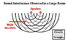
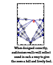 Imagine
that there were simply two speakers in a large auditorium set up so
that there were certain seats that were located along nodal lines for
particular frequencies. When those particular frequencies were sounded
out by the speakers, the people in the seats along those nodal lines
would be at locations of destructive interference and would not hear the
sound from the speakers (at least during the time that those particular
frequencies were being sounded out). Acoustic engineers must take these
factors into account when designing auditorium walls and ceilings. The
walls and ceilings must act as additional "sources" of sound as they
reflect sound waves to all parts of the room so that even when waves
traveling directly from the speakers to a seat undergo destructive
interference, there is still sound reflecting off walls and ceilings to
the same seats. In this sense, the walls and ceilings of a well-designed
auditorium serve to reflect sound in such a way as to fill in those locations where destructive interference might be occurring.

In an incandescent bulb, the vibrations of electrons within the filament
lead to the production of the electromagnetic wave. Several million
times in a second, there are small disruptions of the filament that
result in discontinuities in the waves that they produce. Ultimately,
two different incandescent bulbs are unable to produce light waves that
maintain a constant difference in phase over time. As a result, any
interference pattern that does occur will not endure for a sufficient
length of time to allow the human eye to observe the pattern.

1. Anna Litical is listening to FIZX - 1040 kiloHertz on the dial. FIZX broadcasts from a location of about 78 kilometers from her home. Regrettably for Anna, the presence of a long mountain range with steep cliffs reflects the signal to her home and causes destructive interference. The mountain cliffs are located directly behind her home relative to a line drawn from the broadcasting station to her home. What is the minimum distance that the mountain cliffs are located behind her home? (Assume that the reflected wave does not undergo a phase change upon reflection off the mountain.)
2. Anna Litical is listening to WFIZ when she observes that destructive interference occurs due to reflection of radio waves off an overhead plane. Suppose that destructive interference is observed for plane heights of 161 meters, 207 meters, and 253 meters directly above her home (in additional to other distances as well). WFIZ broadcasts from a location of about 59 kilometers from her home. Determine the frequency at which WFIZ broadcasts their radio signals. (Assume that the reflected wave does not undergo a phase change upon reflection off the plane.)
3. Anna Litical is listening to WBBM - 780 KHz on the radio dial - when she observes destructive interference occurs due to the reflection of radio waves off a plane that is directly above her home. WBBM broadcasts from a location of about 40 miles from her home. Determine the closest possible distance that the plane could be overhead and determine the next three possible heights of the plane. (Assume that the reflected wave does not undergo a phase change upon reflection off the plane.)
| y = |
d = |
m = |
L = |
| y = |
d = |
m = |
L = |
| y = |
d = |
m = |
L = |
| y = |
d = |
m = |
L = |
| y = |
d = |
m = |
L = |
| y = |
d = |
m = |
L = |
| y = |
d = |
m = |
L = |
1.Answer: 657 nm
First, identify known values in terms of their corresponding variable symbol:
(Note: m was chosen as 10 since the y distance corresponds to the distance from the 5th bright band on one side of the central band and the 5th bright band on the other side of the central band.)
L = 10.2 m = 1020 cm y = 22.5 cm m = 10 d = 0.298 mm = 0.0298 cm
Then convert all known values to an identical unit. In this case, cm has been chosen as the unit to use. The converted values are listed in the table above.
Substitute all values into Young's equation and perform calculation of the wavelength. The unit of wavelength is cm.
λ = y • d / ( m • L) λ = ( 22.5 cm ) • ( 0.0298 cm ) / [ ( 10 ) • ( 1020 cm ) ]Finally convert to nanometers using a conversion factor. If there are 109 nm in 1 meter, then there must be 107 nm in the smaller centimeter.
λ = 6.57 x 10⁻⁵ cm
λ = ( 6.57 x 10⁻⁵ cm ) • ( 107 nm / 1 cm ) = 657 nm
2.Answer: 524 nm
First, identify known values in terms of their corresponding variable symbol:
Then convert all known values to an identical unit. In this case, cm has been chosen as the unit to use. The converted values are listed in the table above.
L = 5.87 m = 587 cm y = 8.21 cm m = 4 d = 0.150 mm = 0.0150 cm
Substitute all values into Young's equation and perform calculation of the wavelength. The unit of wavelength is cm.
λ = y • d / ( m • L)Finally convert to nanometers using a conversion factor. If there are 109 nm in 1 meter, then there must be 107 nm in the smaller centimeter.
λ = ( 8.21 cm ) • ( 0.0150 cm ) / [ ( 4 ) • ( 587 cm ) ]
λ = 5.24 x 10⁻⁵ cm
λ = ( 5.24 x 10⁻⁵ cm ) • ( 107 nm / 1 cm ) = 524 nm3.a)
This question simply asks to equate the stated information with the variables of Young's equation and to perform conversions such that all information is in the same unit.
| y = 12.8 cm | d = 0.250 mm | m = 4.5 | L = 8.2 meters |
| y = 12.8 cm | d = 0.0250 cm | m = 4.5 | L = 820 cm |
b)This question simply asks to equate the stated information with the variables of Young's equation and to perform conversions such that all information is in the same unit.
| y = 32.9 cm | d = 50.0 µm | m = 6 | L = 7.65 m |
| y = 32.9 cm | d = 0.00500 cm | m = 6 | L = 765 cm |
c)This question simply asks to equate the stated information with the variables of Young's equation and to perform conversions such that all information is in the same unit.
| y = 8.4 cm | d = 0.25 mm | m = 2.5 | L = 235 cm |
| y = 8.4 cm | d = 0.025 cm | m = 2.5 | L = 235 cm |
d)This question simply asks to equate the stated information with the variables of Young's equation and to perform conversions such that all information is in the same unit.
| y = 98 mm | d = 0.500 mm | m = 3 | L = 525 cm |
| y = 9.8 cm | d = 0.0500 cm | m = 3 | L = 525 cm |
e)This question simply asks to equate the stated information with the variables of Young's equation and to perform conversions such that all information is in the same unit.
| y = 0.1 • L | d = 0.200 mm | m = 10 | L - not stated |
| y = 0.1 • L | d = 0.200 mm | m = 10 | L - not stated |
f)This question simply asks to equate the stated information with the variables of Young's equation and to perform conversions such that all information is in the same unit.
| y = 32.1 cm | d = 25.0 µm | m = 6.5 | L = 6.5 m |
| y = 32.1 cm | d = 0.00250 cm | m = 6.5 | L = 650 cm |
g) This question simply asks to equate the stated information with the variables of Young's equation and to perform conversions such that all information is in the same unit.
| y = 1 cm | d = 0.100 mm | m = 0.5 | L = 300 mm |
| y = 1 cm | d = 0.0100 cm | m = 0.5 | L = 30.0 cm |
h)This question simply asks to equate the stated information with the variables of Young's equation and to perform conversions such that all information is in the same unit.
| y = 3.5 cm | d = 0.050 mm | m = 1 | L = 10.0 m |
| y = 3.5 cm | d = 0.0050 cm | m = 1 | L = 1000 cm |
Other Applications of Two-Point Source Interference
The Big Idea
Before identifying and explaining real-world examples of two-point source interference, the big idea behind it ought to be reviewed. In the second part of Lesson 3, it was noted that two coherent waves traveling along two different paths to the same point will interfere constructively if there is a difference in distance traveled that is equivalent to a whole number of wavelengths. And similarly, two coherent waves traveling along two different paths to the same point will interfere destructively if there is a difference in distance traveled that is equivalent to a half number of wavelengths. The difference in distance traveled by the waves from the two sources to the single point is referred to as the path difference. That is,
Constructive Interference:
|
||
Destructive Interference:
|
The Applications
Given the above principle, the clue to finding two-point source interference in the real world would be to look for situations in which waves from two coherent sources travel along two different paths to the same point. Since the two waves must be coherent, it is best that they can be traced to the same source, but separated into two paths at some point due to passage through two openings or reflection off a barrier. A common example of this involves the interference of radio wave signals that occur at the antenna of a home when radio waves from a very distant transmitting station take two different paths from the station to the home. This is relatively common for homes located near mountain cliffs. In such an instance, waves travel directly from the transmitting station to the antenna and interfere with other waves that reflect off the mountain cliffs behind the home and travel back to the antenna.
Destructive:
|
This same principle of destructive interference of radio signals can be observed when waves from the transmitting source reflect off airplanes that are flying overhead. In this case, there will be a difference in the distance traveled by the wave moving along the direct path to the antenna and the wave that travels along the reflected path off the plane to the antenna. While the interference is momentary (the plane does not remain in a stationary location), it is nonetheless observable. If we suppose that the plane is directly overhead and that the distance from the antenna to the transmitting station is relatively large, then the path difference is simply the height of the plane above the house.

Destructive:
|
A final application of two-point source interference that is discussed here involves the interference of sound waves. All waves, whether light waves, sound waves or water waves, exhibit the same characteristics properties. Waves refract, reflect, diffract and interfere in the same manner according to the same rules. And as such, two coherent sound waves traveling along different paths to the same point will destructively interfere provided that the path difference is equal to a half number of wavelengths.
A relatively common demonstration of sound wave interference can be performed with two speakers in a large room such as an auditorium. If both speakers are hooked up to the same sound source producing a monotone sound, then a sound interference pattern can be observed within the room. If one were to walk along a line parallel to the line connecting the speakers, there would be clear locations of destructive and constructive interference. At locations of destructive interference, the sound intensity would become weak, perhaps even barely noticeable. At locations of constructive interference, the sound intensity would be amplified. These locations would be observed along the line at which one walks at nearly regular intervals of distance.

 Imagine
that there were simply two speakers in a large auditorium set up so
that there were certain seats that were located along nodal lines for
particular frequencies. When those particular frequencies were sounded
out by the speakers, the people in the seats along those nodal lines
would be at locations of destructive interference and would not hear the
sound from the speakers (at least during the time that those particular
frequencies were being sounded out). Acoustic engineers must take these
factors into account when designing auditorium walls and ceilings. The
walls and ceilings must act as additional "sources" of sound as they
reflect sound waves to all parts of the room so that even when waves
traveling directly from the speakers to a seat undergo destructive
interference, there is still sound reflecting off walls and ceilings to
the same seats. In this sense, the walls and ceilings of a well-designed
auditorium serve to reflect sound in such a way as to fill in those locations where destructive interference might be occurring.
Imagine
that there were simply two speakers in a large auditorium set up so
that there were certain seats that were located along nodal lines for
particular frequencies. When those particular frequencies were sounded
out by the speakers, the people in the seats along those nodal lines
would be at locations of destructive interference and would not hear the
sound from the speakers (at least during the time that those particular
frequencies were being sounded out). Acoustic engineers must take these
factors into account when designing auditorium walls and ceilings. The
walls and ceilings must act as additional "sources" of sound as they
reflect sound waves to all parts of the room so that even when waves
traveling directly from the speakers to a seat undergo destructive
interference, there is still sound reflecting off walls and ceilings to
the same seats. In this sense, the walls and ceilings of a well-designed
auditorium serve to reflect sound in such a way as to fill in those locations where destructive interference might be occurring.Why Does Light From Two Light Bulbs Not Form an Interference Pattern?
When the topic of Young's experiment and interference is discussed, the question is often raised: Why doesn't light from two light bulbs undergo interference to produce a two-source interference pattern? Why do I not observe bright and dark fringes along my living room wall from the interference of light from two lamps? The explanation pertains to the nature of ordinary incandescent bulbs and to the necessity of coherent sources. Recall from earlier in this lesson that the importance of coherent light sources was emphasized. Coherent light sources are sources of light that produce waves that have a constant phase difference between them over a significant duration of time. Two waves may have the same frequency and wavelength but be offset from each other in that they are at different points in a complete cycle. For instance, one wave could be at a crest position just prior to the moment in time when the other source is creating a crest. They are said to be out of phase. Yet if they maintain the same difference in phase, they are considered coherent light sources. Even if the sources of light do not stay in step with each other, as long as the amount by which they are out of step remains the same over time, the light sources are said to be coherent. To be coherent, two waves must have the same frequency and there must not be any disruption of their cycle over the course of time.

Check Your Understanding
1. Anna Litical is listening to FIZX - 1040 kiloHertz on the dial. FIZX broadcasts from a location of about 78 kilometers from her home. Regrettably for Anna, the presence of a long mountain range with steep cliffs reflects the signal to her home and causes destructive interference. The mountain cliffs are located directly behind her home relative to a line drawn from the broadcasting station to her home. What is the minimum distance that the mountain cliffs are located behind her home? (Assume that the reflected wave does not undergo a phase change upon reflection off the mountain.)
2. Anna Litical is listening to WFIZ when she observes that destructive interference occurs due to reflection of radio waves off an overhead plane. Suppose that destructive interference is observed for plane heights of 161 meters, 207 meters, and 253 meters directly above her home (in additional to other distances as well). WFIZ broadcasts from a location of about 59 kilometers from her home. Determine the frequency at which WFIZ broadcasts their radio signals. (Assume that the reflected wave does not undergo a phase change upon reflection off the plane.)
3. Anna Litical is listening to WBBM - 780 KHz on the radio dial - when she observes destructive interference occurs due to the reflection of radio waves off a plane that is directly above her home. WBBM broadcasts from a location of about 40 miles from her home. Determine the closest possible distance that the plane could be overhead and determine the next three possible heights of the plane. (Assume that the reflected wave does not undergo a phase change upon reflection off the plane.)
ANSWERS:
1.
Answer: 72.1 m
An important first step is to determine the wavelength of the radio
waves using the v = f • λ where the v value is the speed of light (3 x
108 m/s). Using 1040 kiloHertz or 1.04 x 10⁶ Hz as the frequency, the wavelength is calculated as
λ = v / f = (3 x 10⁸ m/s) / (1.04 x 10⁶ Hz) = 288.46 m
Destructive interference occurs when the path difference is equal to a half-number of wavelengths. The wave traveling the greatest distance must travel past the house to the mountain a distance of d and then back to the house another distance of d. Thus, the path difference is d + d or 2•d.
Destructive interference will occur if the difference in distance
traveled for the direct path compared to the reflected path is some half
number of wavelengths.
By substituting values of wavelength and m = 0.5, 1.5, 2.5, ... into the
above equation, various possible values for the separation distance
between the house and the mountain cliffs can be determined. The minimum
distance occurs when m = 0.5 is used:
2.Answer: 6.52 x 10⁶ Hz or 6.52 MHz
|
|
|
2 • d = 0.5 • (288.46 m) d = 0.5 • (288.46 m) / 2
d = 72.1 m
2.Answer: 6.52 x 10⁶ Hz or 6.52 MHz
The solution strategy to this problem involves using the stated heights
to determine the wavelength of the waves which are interfering at the
antenna. Once the wavelength is determined, the frequency can be
calculated using the v = f • λ equation.
The stated heights each satisfy the criteria that the path difference (between the reflected pathway off the plane and the direct pathway straight to the antenna) is equal to a half number of wavelengths. Since the transmitting station is a relatively far distance from the antenna, the path difference is simply the heights of the plane above the house.
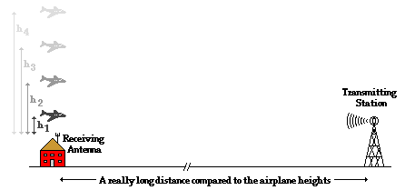
So each of the heights corresponds to m•λ where m can be 0.5, 1.5, 2.5,
3.5, ... . The difference in heights between two adjacent plane
positions is then the difference between using (n + 0.5)•λ and (n +
1.5)•λ as the path difference. A glance at the three positions shown (161 meters, 207 meters, and 253 meters )
reveals that the difference in heights is 46 meters. Thus, the
wavelength is 46 meters. In other words, the path difference for the
first height is 3.5•λ or 161 meters. The path difference for the second
height is 4.5•λ or 207 meters. And the path difference for the third
height is 5.5•λ or 253 meters.
Once the wavelength is determined, the frequency can be computed:
3.Answers: 192 m , 577 m , 962 m and 1346 m
The stated heights each satisfy the criteria that the path difference (between the reflected pathway off the plane and the direct pathway straight to the antenna) is equal to a half number of wavelengths. Since the transmitting station is a relatively far distance from the antenna, the path difference is simply the heights of the plane above the house.

Once the wavelength is determined, the frequency can be computed:
f = v / λ f = (3 x 10⁸ m/s) / (46 m)
f = 6.52 x 10⁶ Hz or 6.52 MHz
3.Answers: 192 m , 577 m , 962 m and 1346 m
An important first step is to determine the wavelength of the radio
waves using the v = f • λ where the v value is the speed of light (3 x
108 m/s). Using 780 kiloHertz or 7.80 x 10⁵ Hz as the frequency, the wavelength is calculated as
λ = v / f = (3 x 10⁸ m/s) / (7.80 x 10⁵ Hz) = 384.62 m
Destructive interference occurs when the path difference is equal to a half-number
of wavelengths. The wave traveling the greatest distance must travel
from the transmitting tower to the plane above the house and then
reflect off the plane down to the house. This wave travels an extra
distance of h compared to the wave which travels from the transmitting tower directly to the house. Thus, the path difference is h.

Destructive interference will occur if the difference in distance
traveled for the direct path compared to the reflected path is some half
number of wavelengths.
By substituting values of wavelength and m = 0.5, 1.5, 2.5, ... into the
above equation, various possible values for the height of the plane
above the house can be determined. The minimum height occurs when m =
0.5 is used:
Values for the next three heights are:

|
|
|
h = 0.5 • (384.62 m) d = 192 mThe next three possible heights can be determined using the next three half numbers - 1.5, 2.5, and 3.5.
Values for the next three heights are:
h2 = 1.5 • (384.62 m) = 577 m h3 = 2.5 • (384.62 m) = 962 m
h4 = 3.5 • (384.62 m) = 1346 m
No comments:
Post a Comment