This is saikrishna !!!!!!!!!!!!!!!
thank you for visiting this website !!!!!!!!!
Light Waves and Color - Lesson 1 - How Do We Know Light is a Wave?
Wavelike Behaviors of Light
Light exhibits certain behaviors that are characteristic of any wave and would be difficult to explain with a purely particle-view. Light reflects in the same manner that any wave would reflect. Light refracts in the same manner that any wave would refract. Light diffracts in the same manner that any wave would diffract. Light undergoes interference in the same manner that any wave would interfere. And light exhibits the Doppler effect just as any wave would exhibit the Doppler effect. Light behaves in a way that is consistent with our conceptual and mathematical understanding of waves. Since light behaves like a wave, one would have good reason to believe that it might be a wave. In Lesson 1, we will investigate the variety of behaviors, properties and characteristics of light that seem to support the wave model of light. On this page, we will focus on three specific behaviors - reflection, refraction and diffraction.
A wave doesn't just stop when it reaches the end of the medium. Rather, a wave will undergo certain behaviors when it encounters the end of the medium. Specifically, there will be some reflection off the boundary and some transmission into the new medium. The transmitted wave undergoes refraction (or bending) if it approaches the boundary at an angle. If the boundary is merely an obstacle implanted within the medium, and if the dimensions of the obstacle are smaller than the wavelength of the wave, then there will be very noticeable diffraction of the wave around the object. Each one of these behaviors - reflection, refraction and diffraction - is characterized by specific conceptual principles and mathematical equations. The reflection, refraction, and diffraction of waves were first introduced in Unit 10 of The Physics Classroom Tutorial. In Unit 11 of The Physics Classroom Tutorial, the reflection, refraction, and diffraction of sound waves was discussed. Now we will see how light waves demonstrate their wave nature by reflection, refraction and diffraction.
Reflection of Light Waves
All waves are known to undergo reflection or the bouncing off of an obstacle. Most people are very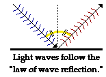 accustomed
to the fact that light waves also undergo reflection. The reflection of
light waves off of a mirrored surface results in the formation of an
image. One characteristic of wave reflection is that the angle at which
the wave approaches a flat reflecting surface is equal to the angle at
which the wave leaves the surface. This characteristic is observed for
water waves and sound waves. It is also observed for light waves. Light,
like any wave, follows the law of reflection when bouncing off
surfaces. The reflection of light waves will be discussed in more detail
in Unit 13 of The Physics Classroom. For now, it is enough to say that the reflective behavior of light provides evidence for the wavelike nature of light.
accustomed
to the fact that light waves also undergo reflection. The reflection of
light waves off of a mirrored surface results in the formation of an
image. One characteristic of wave reflection is that the angle at which
the wave approaches a flat reflecting surface is equal to the angle at
which the wave leaves the surface. This characteristic is observed for
water waves and sound waves. It is also observed for light waves. Light,
like any wave, follows the law of reflection when bouncing off
surfaces. The reflection of light waves will be discussed in more detail
in Unit 13 of The Physics Classroom. For now, it is enough to say that the reflective behavior of light provides evidence for the wavelike nature of light.Refraction of Light Waves
All waves are known to undergo refraction when they pass from one medium to another medium. That is, when a wavefront crosses the boundary between two media, the direction that the wavefront is moving undergoes a sudden change; the path is "bent." This behavior of wave refraction can be described by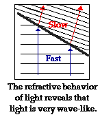 both
conceptual and mathematical principles. First, the direction of
"bending" is dependent upon the relative speed of the two media. A wave
will bend one way when it passes from a medium in which it travels
slowly into a medium in which it travels fast; and if moving from a fast medium to a slow medium,
the wavefront will bend in the opposite direction. Second, the amount
of bending is dependent upon the actual speeds of the two media on each
side of the boundary. The amount of bending is a measurable behavior
that follows distinct mathematical equations. These equations are based
upon the speeds of the wave in the two media and the angles at which the
wave approaches and departs from the boundary. Light, like any wave, is
known to refract as it passes from one medium into another medium. In
fact, a study of the refraction of light reveals that its refractive
behavior follows the same conceptual and mathematical rules that govern
the refractive behavior of other waves such as water waves and sound
waves. The refraction of light waves will be discussed in more detail in
Unit 14 of The Physics Classroom Tutorial. For now, it is enough to say that the refractive behavior of light provides evidence for the wavelike nature of light.
both
conceptual and mathematical principles. First, the direction of
"bending" is dependent upon the relative speed of the two media. A wave
will bend one way when it passes from a medium in which it travels
slowly into a medium in which it travels fast; and if moving from a fast medium to a slow medium,
the wavefront will bend in the opposite direction. Second, the amount
of bending is dependent upon the actual speeds of the two media on each
side of the boundary. The amount of bending is a measurable behavior
that follows distinct mathematical equations. These equations are based
upon the speeds of the wave in the two media and the angles at which the
wave approaches and departs from the boundary. Light, like any wave, is
known to refract as it passes from one medium into another medium. In
fact, a study of the refraction of light reveals that its refractive
behavior follows the same conceptual and mathematical rules that govern
the refractive behavior of other waves such as water waves and sound
waves. The refraction of light waves will be discussed in more detail in
Unit 14 of The Physics Classroom Tutorial. For now, it is enough to say that the refractive behavior of light provides evidence for the wavelike nature of light.Diffraction of Light Waves
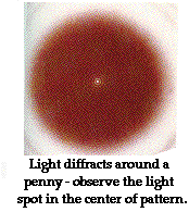
Reflection involves a change in direction of waves when they bounce off a barrier. Refraction of waves involves a change in the direction of waves as they pass from one medium to another. And diffraction involves a change in direction of waves as they pass through an opening or around an obstacle in their path. Water waves have the ability to travel around corners, around obstacles and through openings. Sound waves do the same. But what about light? Do light waves bend around obstacles and through openings? If they do, then it would provide still more evidence to support the belief that light behaves as a wave.When light encounters an obstacle in its path, the obstacle blocks the light and tends to cause the formation of a shadow in the region behind the obstacle. Light does not exhibit a very noticeable ability to bend
 around
the obstacle and fill in the region behind it with light. Nonetheless,
light does diffract around obstacles. In fact, if you observe a shadow
carefully, you will notice that its edges are extremely fuzzy.
Interference effects occur due to the diffraction of light around
different sides of the object, causing the shadow of the object to be
fuzzy. This is often demonstrated in a Physics classroom with a laser
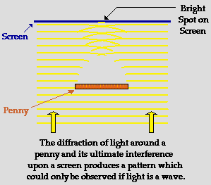
light and penny demonstration. Light diffracting around the right edge
of a penny can constructively and destructively interfere with light
diffracting around the left edge of the penny. The result is that an
interference pattern is created; the pattern consists of alternating
rings of light and darkness. Such a pattern is only noticeable if a
narrow beam of monochromatic light (i.e., single wavelength light) is
passed directed at the penny. The photograph at the right shows an
interference pattern created in this manner. Since, light waves are
diffracting around the edges of the penny, the waves are broken up into
different wavefronts that converge at a point on a screen to produce the
interference pattern shown in the photograph. Can you explain this
phenomenon with a strictly particle-view of light? This amazing penny
diffraction demonstration provides another reason why believing that
light has a wavelike nature makes cents (I mean "sense"). These
interference effects will be discussed in more detail later in this lesson.
Light behaves as a wave - it undergoes reflection, refraction, and diffraction just like any wave would. Yet there is still more reason to believe in the wavelike nature of light. Continue with Lesson 1 to learn about more behaviors that could never be explained by a strictly particle-view of light.
Two Point Source Interference:
Wave interference is a phenomenon that occurs when two waves meet while traveling along the same medium. The interference of waves causes the medium to take on a shape that results from the net effect of the two individual waves upon the particles of the medium. Wave interference can be constructive or destructive in nature. Constructive interference occurs at any location along the medium where the two interfering waves have a displacement in the same direction. For example, if at a given instant in time and location along the medium, the crest of one wave meets the crest of a second wave, they will interfere in such a manner as to produce a "super-crest." Similarly, the interference of a trough and a trough interfere constructively to produce a "super-trough." Destructive interference occurs at any location along the medium where the two interfering waves have a displacement in the opposite direction. For example, the interference of a crest with a trough is an example of destructive interference. Destructive interference has the tendency to decrease the resulting amount of displacement of the medium. Interference principles were first introduced in Unit 10 of The Physics Classroom Tutorial. The principles were subsequently applied to the interference of sound waves in Unit 11 of The Physics Classroom Tutorial.A defining moment in the history of the debate concerning the nature of light occurred in the early years of the nineteenth century. Thomas Young showed that an interference pattern results when light from two sources meets up while traveling through the same medium. To understand Young's experiment, it is important to back up a few steps and discuss the interference of water waves that originate from two points.
In Unit 10, the value of a ripple tank in the study of water wave behavior was introduced and discussed. If an object bobs up and down in the water, a series water waves in the shape of concentric circles will be produced within the water. If two objects bob up and down with the same frequency at two different points,
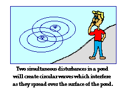 then
two sets of concentric circular waves will be produced on the surface
of the water. These concentric waves will interfere with each other as
they travel across the surface of the water. If you have ever
simultaneously tossed two pebbles into a lake (or somehow simultaneously
disturbed the lake in two locations), you undoubtedly noticed the
interference of these waves. The crest of one wave will interfere
constructively with the crest of the second wave to produce a large
upward displacement. And the trough of one wave will interfere
constructively with the trough of the second wave to produce a large
downward displacement. And finally the crest of one wave will interfere
destructively with the trough of the second wave to produce no
displacement. In a ripple tank, this constructive and destructive
interference can be easily controlled and observed. It represents a
basic wave behavior that can be expected of any type of wave.
then
two sets of concentric circular waves will be produced on the surface
of the water. These concentric waves will interfere with each other as
they travel across the surface of the water. If you have ever
simultaneously tossed two pebbles into a lake (or somehow simultaneously
disturbed the lake in two locations), you undoubtedly noticed the
interference of these waves. The crest of one wave will interfere
constructively with the crest of the second wave to produce a large
upward displacement. And the trough of one wave will interfere
constructively with the trough of the second wave to produce a large
downward displacement. And finally the crest of one wave will interfere
destructively with the trough of the second wave to produce no
displacement. In a ripple tank, this constructive and destructive
interference can be easily controlled and observed. It represents a
basic wave behavior that can be expected of any type of wave.Two-Point Source Interference Patterns
The interference of two sets of periodic and concentric waves with the same frequency produces an interesting pattern in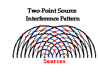 a
ripple tank. The diagram at the right depicts an interference pattern
produced by two periodic disturbances. The crests are denoted by the
thick lines and the troughs are denoted by the thin lines. Thus,
constructive interference occurs wherever a thick line meets a thick
line or a thin line meets a thin line; this type of interference results
in the formation of an antinode. The antinodes
are denoted by a red dot. Destructive interference occurs wherever a
thick line meets a thin line; this type of interference results in the
formation of a node. The nodes
are denoted by a blue dot. The pattern is a standing wave pattern,
characterized by the presence of nodes and antinodes that are "standing
still" - i.e., always located at the same position on the medium. The
antinodes (points where the waves always interfere constructively) seem
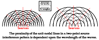
to be located along lines - creatively called antinodal lines. The nodes also fall along lines - called nodal lines.
The two-point source interference pattern is characterized by a pattern
of alternating nodal and antinodal lines. There is a central line in
the pattern - the line that bisects the line segment that is drawn
between the two sources is an antinodal line. This central antinodal line
is a line of points where the waves from each source always reinforce
each other by means of constructive interference. The nodal and
antinodal lines are included on the diagram below.
a
ripple tank. The diagram at the right depicts an interference pattern
produced by two periodic disturbances. The crests are denoted by the
thick lines and the troughs are denoted by the thin lines. Thus,
constructive interference occurs wherever a thick line meets a thick
line or a thin line meets a thin line; this type of interference results
in the formation of an antinode. The antinodes
are denoted by a red dot. Destructive interference occurs wherever a
thick line meets a thin line; this type of interference results in the
formation of a node. The nodes
are denoted by a blue dot. The pattern is a standing wave pattern,
characterized by the presence of nodes and antinodes that are "standing
still" - i.e., always located at the same position on the medium. The
antinodes (points where the waves always interfere constructively) seem
to be located along lines - creatively called antinodal lines. The nodes also fall along lines - called nodal lines.
The two-point source interference pattern is characterized by a pattern
of alternating nodal and antinodal lines. There is a central line in
the pattern - the line that bisects the line segment that is drawn
between the two sources is an antinodal line. This central antinodal line
is a line of points where the waves from each source always reinforce
each other by means of constructive interference. The nodal and
antinodal lines are included on the diagram below.A two-point source interference pattern always has an alternating pattern of nodal and antinodal lines. There are however some features of the pattern that can be modified. First, a change in wavelength (or frequency) of the source will alter the number of lines in the pattern and alter the proximity or closeness of the lines. An increase in frequency will result in more lines per centimeter and a smaller distance between each consecutive line. And a decrease in frequency will result in fewer lines per centimeter and a greater distance between each consecutive line.
Two-Point Source Light Interference Patterns
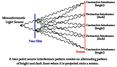
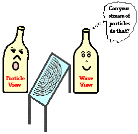
Any type of wave, whether it be a water wave or a sound wave should produce a two-point source interference pattern if the two sources periodically disturb the medium at the same frequency. Such a pattern is always characterized by a pattern of alternating nodal and antinodal lines. Of course, the question should arise and indeed did arise in the early nineteenth century: Can light produce a two-point source interference pattern? If light is found to produce such a pattern, then it will provide more evidence in support of the wavelike nature of light.Before we investigate the evidence in detail, let's discuss what one might observe if light were to undergo two-point source interference. What would happen if a "crest" of one light wave interfered with a "crest" of a second light wave? And what would happen if a "trough" of one light wave interfered with a "trough" of a second light wave? And finally, what would happen if a "crest" of one light wave interfered with a "trough" of a second light wave?
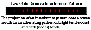
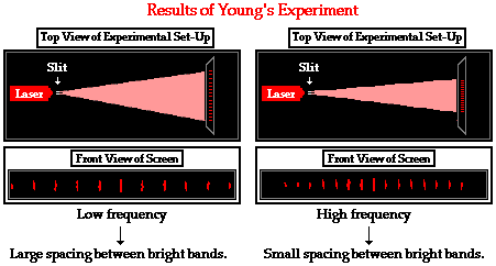
Whenever light constructively interferes (such as when a crest meeting a crest or a trough meeting a trough), the two waves act to reinforce one another and to produce a "super light wave." On the other hand, whenever light destructively interferes (such as when a crest meets a trough), the two waves act to destroy each other and produce no light wave. Thus, the two-point source interference pattern would still consist of an alternating pattern of antinodal lines and nodal lines. However for light waves, the antinodal lines are equivalent to bright lines and the nodal lines are equivalent to dark lines. If such an interference pattern could be created by two light sources and projected onto a screen, then there ought to be an alternating pattern of dark and bright bands on the screen. And since the central line in such a pattern is an antinodal line, the central band on the screen ought to be a bright band.
Thin Film Interference
Perhaps you have witnessed streaks of color on a car windshield shortly after it has been swiped by a windshield wiper or a squeegee at a gas station. The momentary streaks of color are the result of interference of light by the very thin film of water or soap that remains on the windshield. Or perhaps you have witnessed streaks of color in a thin film of oil resting upon a water puddle or concrete driveway. These streaks of color are the result of the interference of light by the very thin film of oil that is spread over the water surface. This form of interference is commonly called thin film interference and provides another line of evidence for the wave behavior of light.
Light wave interference results when two waves are traveling through a medium and meet up at the same location. So what exactly is causing this thin film interference? What is the source of the two waves? When a wave (light waves included) reaches the boundary between two media, a portion of the wave reflects off the boundary and a portion is transmitted across the boundary. The reflected portion of the wave remains in the original medium. The transmitted portion of the wave enters the new medium and continues traveling through it until it reaches a subsequent boundary. If the new medium is a thin film, then the transmitted wave does not travel far before it reaches a new boundary and undergoes the usual
 reflection
and transmission behavior. Thus, there are two waves that emerge from
the film - one wave that is reflected off the top of the film (wave 1 in
the diagram) and the other wave that reflects off the bottom of the
film (wave 2 in the diagram).
reflection
and transmission behavior. Thus, there are two waves that emerge from
the film - one wave that is reflected off the top of the film (wave 1 in
the diagram) and the other wave that reflects off the bottom of the
film (wave 2 in the diagram).These two waves could interfere constructively if they meet two conditions. One condition is that the two waves must be relatively close together such that their crests and troughs can meet up with each other and cause the interference. To meet this condition, the light must be incident at angles close to zero with respect to the normal. (This is not shown in the diagram above in order to space out the waves for clarity sake.) A second condition that must be met is that the wave that travels through the film and back into the original medium must have traveled just the right distance such that it is in phase with the other reflected wave. Two waves that are in phase are waves that are always at the same point on their wave cycle. That is, the two waves must be forming crests at the same location and at the same moment in time and forming troughs at the same location and at the same moment in time. In order for the second condition to occur, the thickness of the film must be just perfect.
If wave 1 and wave 2 meet these two conditions as they reflect and exit the film, then they will constructively interfere. As will be learned in Lesson 2, light that is visible to our eyes consists of a collection of light waves of varying wavelength. Each wavelength is characterized by its own color. So a red light wave has a different wavelength than an orange light wave that has a different wavelength than a yellow light wave. While the thickness of a film at a given location may not allow a red and an orange light wave to emerge from the film in phase, it may be just perfect to allow a yellow light wave to emerge in phase. So at a given location on the film, the yellow light wave undergoes constructive interference and becomes brighter than the other colors within the incident light. As such, the film appears yellow when viewed by incident sunlight. Other locations of the film may be just perfect to constructively reinforce red light. And still others area of the film may be of perfect thickness for the constructive reinforcement of green light. Because different locations of the film may be of appropriate thickness to reinforce different colors of light, the thin film will show streaks of color when viewed from above.
While the mathematics of thin film interference can become quite complicated, it is clear from this discussion that thin film interference is another phenomenon that can only be explained using a wave model of light.
Polarization
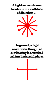 The transverse nature of an electromagnetic wave is quite different from any other type of wave that has been discussed in The Physics Classroom Tutorial.
Let's suppose that we use the customary slinky to model the behavior of
an electromagnetic wave. As an electromagnetic wave traveled towards
you, then you would observe the vibrations of the slinky occurring in
more than one plane of vibration. This is quite different than what you
might notice if you were to look along a slinky and observe a slinky
wave traveling towards you. Indeed, the coils of the slinky would be
vibrating back and forth as the slinky approached; yet these vibrations
would occur in a single plane of space. That is, the coils of the slinky
might vibrate up and down or left and right. Yet regardless of their
direction of vibration, they would be moving along the same linear
direction as you sighted along the slinky. If a slinky wave were an
electromagnetic wave, then the vibrations of the slinky would occur in
multiple planes. Unlike a usual slinky wave, the electric and magnetic
vibrations of an electromagnetic wave occur in numerous planes. A light
wave that is vibrating in more than one plane is referred to as unpolarized light.
Light emitted by the sun, by a lamp in the classroom, or by a candle
flame is unpolarized light. Such light waves are created by electric
charges that vibrate in a variety of directions, thus creating an
electromagnetic wave that vibrates in a variety of directions. This
concept of unpolarized light is rather difficult to visualize. In
general, it is helpful to picture unpolarized light as a wave that has
an average of half its vibrations in a horizontal plane and half of its
vibrations in a vertical plane.
The transverse nature of an electromagnetic wave is quite different from any other type of wave that has been discussed in The Physics Classroom Tutorial.
Let's suppose that we use the customary slinky to model the behavior of
an electromagnetic wave. As an electromagnetic wave traveled towards
you, then you would observe the vibrations of the slinky occurring in
more than one plane of vibration. This is quite different than what you
might notice if you were to look along a slinky and observe a slinky
wave traveling towards you. Indeed, the coils of the slinky would be
vibrating back and forth as the slinky approached; yet these vibrations
would occur in a single plane of space. That is, the coils of the slinky
might vibrate up and down or left and right. Yet regardless of their
direction of vibration, they would be moving along the same linear
direction as you sighted along the slinky. If a slinky wave were an
electromagnetic wave, then the vibrations of the slinky would occur in
multiple planes. Unlike a usual slinky wave, the electric and magnetic
vibrations of an electromagnetic wave occur in numerous planes. A light
wave that is vibrating in more than one plane is referred to as unpolarized light.
Light emitted by the sun, by a lamp in the classroom, or by a candle
flame is unpolarized light. Such light waves are created by electric
charges that vibrate in a variety of directions, thus creating an
electromagnetic wave that vibrates in a variety of directions. This
concept of unpolarized light is rather difficult to visualize. In
general, it is helpful to picture unpolarized light as a wave that has
an average of half its vibrations in a horizontal plane and half of its
vibrations in a vertical plane.It is possible to transform unpolarized light into polarized light. Polarized light waves are light waves in which the vibrations occur in a single plane. The process of transforming unpolarized light into polarized light is known as polarization. There are a variety of methods of polarizing light. The four methods discussed on this page are:
- Polarization by Transmission
- Polarization by Reflection
- Polarization by Refraction
- Polarization by Scattering
Polarization by Use of a Polaroid Filter
The most common method of polarization involves the use of a Polaroid filter. Polaroid filters are made of a special material that is capable of blocking one of the two planes of vibration of an electromagnetic wave. (Remember, the notion of two planes or directions of vibration is merely a simplification that helps us to visualize the wavelike nature of the electromagnetic wave.) In this sense, a Polaroid serves as a device that filters out one-half of the vibrations upon transmission of the light through the filter. When unpolarized light is transmitted through a Polaroid filter, it emerges with one-half the intensity and with vibrations in a single plane; it emerges as polarized light.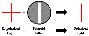
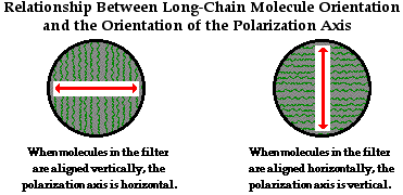
A Polaroid filter is able to polarize light because of the chemical composition of the filter material. The filter can be thought of as having long-chain molecules that are aligned within the filter in the same direction. During the fabrication of the filter, the long-chain molecules are stretched across the filter so that each molecule is (as much as possible) aligned in say the vertical direction. As unpolarized light strikes the filter, the portion of the waves vibrating in the vertical direction are absorbed by the filter. The general rule is that the electromagnetic vibrations that are in a direction parallel to the alignment of the molecules are absorbed.
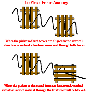
The alignment of these molecules gives the filter a polarization axis. This polarization axis extends across the length of the filter and only allows vibrations of the electromagnetic wave that are parallel to the axis to pass through. Any vibrations that are perpendicular to the polarization axis are blocked by the filter. Thus, a Polaroid filter with its long-chain molecules aligned horizontally will have a polarization axis aligned vertically. Such a filter will block all horizontal vibrations and allow the vertical vibrations to be transmitted (see diagram above). On the other hand, a Polaroid filter with its long-chain molecules aligned vertically will have a polarization axis aligned horizontally; this filter will block all vertical vibrations and allow the horizontal vibrations to be transmitted.

Polarization by Reflection
Unpolarized light can also undergo polarization by reflection off of nonmetallic surfaces. The extent to which polarization occurs is dependent upon the angle at which the light approaches the surface and upon the material that the surface is made of. Metallic surfaces reflect light with a variety of vibrational directions; such reflected light is unpolarized. However, nonmetallic surfaces such as asphalt roadways, snowfields and water reflect light such that there is a large concentration of vibrations in a plane parallel to the reflecting surface. A person viewing objects by means of light reflected off of nonmetallic surfaces will often perceive a glare if the extent of polarization is large. Fishermen are familiar with this glare since it prevents them from seeing fish that lie below the water. Light reflected off a lake is partially polarized in a direction parallel to the water's surface. Fishermen know that the use of glare-reducing sunglasses with the proper polarization axis allows for the blocking of this partially polarized light. By blocking the plane-polarized light, the glare is reduced and the fisherman can more easily see fish located under the water.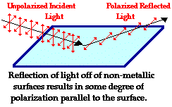
Polarization by Refraction
Polarization can also occur by the refraction of light. Refraction occurs when a beam of light passes from one material into another material. At the surface of the two materials, the path of the beam changes its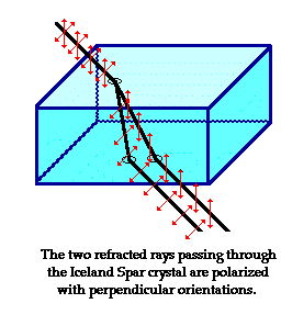 direction.
The refracted beam acquires some degree of polarization. Most often,
the polarization occurs in a plane perpendicular to the surface. The
polarization of refracted light is often demonstrated in a Physics class
using a unique crystal that serves as a double-refracting crystal.
Iceland Spar, a rather rare form of the mineral calcite, refracts
incident light into two different paths. The light is split
into two beams upon entering the crystal. Subsequently, if an object is
viewed by looking through an Iceland Spar crystal, two images will be
seen. The two images are the result of the double refraction of light.
Both refracted light beams are polarized - one in a direction parallel
to the surface and the other in a direction perpendicular to the
surface. Since these two refracted rays are polarized with a
perpendicular orientation, a polarizing filter can be used to completely
block one of the images. If the polarization axis of the filter is
aligned perpendicular to the plane of polarized light, the light is
completely blocked by the filter; meanwhile the second image is as
bright as can be. And if the filter is then turned 90-degrees in either
direction, the second image reappears and the first image disappears.
Now that's pretty neat observation that could never be observed if light
did not exhibit any wavelike behavior.
direction.
The refracted beam acquires some degree of polarization. Most often,
the polarization occurs in a plane perpendicular to the surface. The
polarization of refracted light is often demonstrated in a Physics class
using a unique crystal that serves as a double-refracting crystal.
Iceland Spar, a rather rare form of the mineral calcite, refracts
incident light into two different paths. The light is split
into two beams upon entering the crystal. Subsequently, if an object is
viewed by looking through an Iceland Spar crystal, two images will be
seen. The two images are the result of the double refraction of light.
Both refracted light beams are polarized - one in a direction parallel
to the surface and the other in a direction perpendicular to the
surface. Since these two refracted rays are polarized with a
perpendicular orientation, a polarizing filter can be used to completely
block one of the images. If the polarization axis of the filter is
aligned perpendicular to the plane of polarized light, the light is
completely blocked by the filter; meanwhile the second image is as
bright as can be. And if the filter is then turned 90-degrees in either
direction, the second image reappears and the first image disappears.
Now that's pretty neat observation that could never be observed if light
did not exhibit any wavelike behavior.Polarization by Scattering
Polarization also occurs when light is scattered while traveling through a medium. When light strikes the atoms of a material, it will often set the electrons of those atoms into vibration. The vibrating electrons then produce their own electromagnetic wave that is radiated outward in all directions. This newly generated wave strikes neighboring atoms, forcing their electrons into vibrations at the same original frequency. These vibrating electrons produce another electromagnetic wave that is once more radiated outward in all directions. This absorption and reemission of light waves causes the light to be scattered about the medium. (This process of scattering contributes to the blueness of our skies, a topic to be discussed later.) This scattered light is partially polarized. Polarization by scattering is observed as light passes through our atmosphere. The scattered light often produces a glare in the skies. Photographers know that this partial polarization of scattered light leads to photographs characterized by a washed-out sky. The problem can easily be corrected by the use of a Polaroid filter. As the filter is rotated, the partially polarized light is blocked and the glare is reduced. The photographic secret of capturing a vivid blue sky as the backdrop of a beautiful foreground lies in the physics of polarization and Polaroid filters.Applications of Polarization
Polarization has a wealth of other applications besides their use in glare-reducing sunglasses. In industry, Polaroid filters are used to perform stress analysis tests on transparent plastics. As light passes through a plastic, each color of visible light is polarized with its own orientation. If such a plastic is placed between two polarizing plates, a colorful pattern is revealed. As the top plate is turned, the color pattern changes as new colors become blocked and the formerly blocked colors are transmitted. A common Physics demonstration involves placing a plastic protractor between two Polaroid plates and placing them on top of an overhead projector. It is known that structural stress in plastic is signified at locations where there is a large concentration of colored bands. This location of stress is usually the location where structural failure will most likely occur. Perhaps you wish that a more careful stress analysis were performed on the plastic case of the CD that you recently purchased.Polarization is also used in the entertainment industry to produce and show 3-D movies. Three-dimensional movies are actually two movies being shown at the same time through two projectors. The two movies are filmed from two slightly different camera locations. Each individual movie is then projected from different sides of the audience onto a metal screen. The movies are projected through a polarizing filter. The polarizing filter used for the projector on the left may have its polarization axis aligned horizontally while the polarizing filter used for the projector on the right would have its polarization axis aligned vertically. Consequently, there are two slightly different movies being projected onto a screen. Each movie is cast by light that is polarized with an orientation perpendicular to the other movie. The audience then wears glasses that have two Polaroid filters. Each filter has a different polarization axis - one is horizontal and the other is vertical. The result of this arrangement of projectors and filters is that the left eye sees the movie that is projected from the right projector while the right eye sees the movie that is projected from the left projector. This gives the viewer a perception of depth.
Our model of the polarization of light provides some substantial support for the wavelike nature of light. It would be extremely difficult to explain polarization phenomenon using a particle view of light. Polarization would only occur with a transverse wave. For this reason, polarization is one more reason why scientists believe that light exhibits wavelike behavior.
In the demonstration, a polaroid filter is placed upon the glass panel of a classroom style overhead projector. Light passing through the filter becomes polarized. Different sectors of the taped glass will rotate the axes of polarization of the different wavelengths of light different amounts. A second filter is then placed over the taped glass. This second filter permits passage of wavelengths (i.e. colors) of light whose axis of polarization line up with the transmitting axis of the filter; other wavelengths are blocked. Thus, different sectors appear different colors when viewed through both filters.
Check Your Understanding

ANSWERS:
1.The first filter will polarize the light, blocking one-half of its vibrations. The second filter will have no affect on the light. Being aligned parallel to the first filter, the second filter will let the same light waves through.
2.Answer: Parallel
Reflected light becomes partially polarized in a plane which is parallel to the reflecting surface.
3.Answer: A
Referring to the above question, the glare is the result of a large concentration of light aligned parallel to the water surface. To block such plane-polarized light, a filter with a vertically aligned polarization axis must be used.
No comments:
Post a Comment